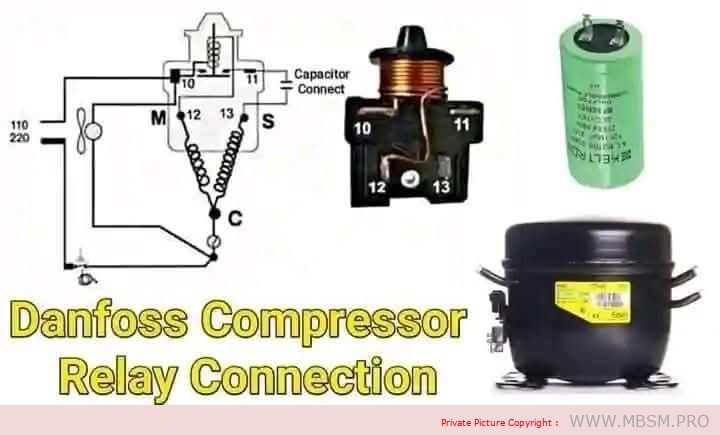
Danfoss Relay Connection Diagram for the Electric Compressor in Refrigeration Systems
Below is a detailed explanation of the components and connection diagram of the Danfoss relay for the electric compressor used in refrigeration systems:
1. Components of the Diagram
- Compressor:
- The compressor is the heart of the refrigeration system, responsible for compressing the refrigerant (freon) and circulating it through the system.
- Relay:
- The relay is used to provide additional electrical current to the start terminal (S) of the compressor, helping it start smoothly.
- Capacitor:
- The capacitor improves the compressor’s torque during startup, reducing the load on the electric motor.
- Electrical Circuit Diagram:
- The diagram shows how the compressor terminals (C, S, R) are connected to the relay, capacitor, and power source.
2. Compressor Terminal Connections
- C (Common):
- The common terminal connected to both the run and start windings.
- R (Run):
- The terminal responsible for continuous operation of the compressor after startup.
- S (Start):
- The terminal responsible for starting the compressor with the help of the relay and capacitor.
3. Steps to Connect the Relay to the Compressor
A. Connecting the Capacitor:
- The capacitor is connected between the S (Start) terminal and the R (Run) terminal to support startup torque.
B. Connecting the Relay:
- Terminals 10 and 11:
- Connected to the power source and the run resistor.
- Terminals 12 and 13:
- Connected to the compressor terminals: S (Start) and C (Common).
C. Power Supply:
- The circuit is powered by a 110V or 220V source (depending on the system used).
4. How the Relay Works
- When power is connected, the relay sends additional current to the start terminal (S) via the capacitor.
- Once the compressor starts running, the relay automatically cuts off the current to the start terminal.
- The compressor continues to operate through the current flowing to the run terminal (R).
5. Importance of Correct Relay Connection
- Compressor Protection:
- Ensures safe compressor operation during startup.
- Energy Saving:
- The relay cuts off the startup current after operation to avoid overload.
- Performance Improvement:
- Helps stabilize compressor operation.
6. Verification Steps After Connection
A. Checking Terminal Connections (C, R, S):
- Use a resistance meter (ohmmeter) to verify correct terminal connections.
B. Testing the Relay:
- Ensure the relay sends startup current when powered.
C. Testing the Capacitor:
- Measure the capacitor’s capacitance (microfarads) using a capacitor tester.
D. Running the Compressor:
- Start the system and check for stable compressor operation.
- Listen for noise: If it is loud, there may be a connection error.
7. Common Faults and Solutions
A. Compressor Fails to Start:
- Cause: Faulty relay or capacitor.
- Solution: Test the relay and capacitor and replace them if necessary.
B. Compressor Runs Briefly and Stops:
- Cause: High current or excessive load.
- Solution: Ensure the external capacitor is clean and there is proper airflow around the unit.
C. Incorrect Connection:
- Cause: Swapped terminals (C, R, S).
- Solution: Use a resistance meter to accurately identify the terminals.
8. Important Tip
- Ensure:
- Terminals are connected correctly according to the diagram.
- Use a capacitor that matches the compressor’s specifications.
- Test the relay before installation to ensure no internal damage.
Conclusion
Correctly connecting the Danfoss relay is crucial for ensuring safe and efficient compressor operation in refrigeration systems. Follow the diagram carefully and perform the necessary tests to avoid malfunctions and improve system performance.


| Attachment | Type | Link |
|---|---|---|
| -Mbsm.pro-Danfoss-Compressor-Relay-Capacitor-Connection | image/jpeg | Get Link |
 | Image | View Image |


