www.mbsm.pro , Quelle est la différence entre le SDS PLUS et le SDS MAX ?

Quelle est la différence entre le SDS PLUS et le SDS MAX ?

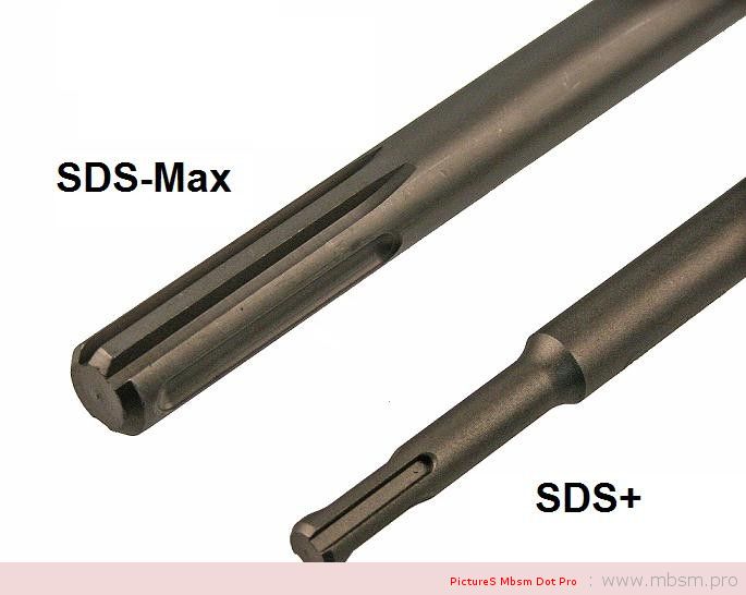
Lorsque vous choisissez un outil, vous aurez donc le choix entre la fixation par mandrin classique (avec ou sans clé de serrage) et par mandrin SDS avec les variantes SDS PLUS et SDS MAX.
Attention, vos accessoires classiques ne seront pas adaptés aux système SDS et inversement ! Le système SDS accueille en effet des mèches/forets avec cannelures qui s’encastrent dans le mandrin et permettent une fixation plus fiable que les forets classiques qui finissent par «glisser dans le mandrin», particulièrement lors de gros travaux (forage / percussion sur de la pierre).


Le système SDS PLUS a été développé pour effectuer une fixation rapide des forets pour des perforateurs de diamètre maximum des forets de 17mm. La plupart des travaux de perforation standard pouvant être assuré par les  perforateurs allant jusqu’à 4kg, le système SDS PLUS est le plus répandu à ce jour.


Le système SDS MAX est quand à lui réservé aux gros travaux ou aux travaux intensifs. Idéal pour les professionnels du bâtiment et de la construction, il est adapté pour les perforateurs de plus de 5kg avec des forêts possédant un emmanchement de minimum 17mn de diamètre et 3 cannelures pour une fixation extrème.

Difference-SDS-plus-et-SDS-Max-mbsm-dot-pro.jpg (47 KB)

Difference-SDS-plus-et-SDS-Max-mbsm-dot-pro.jpg (38 KB)

Difference-SDS-plus-et-SDS-Max-mbsm-dot-pro.jpg (38 KB)

Difference-SDS-plus-et-SDS-Max-mbsm-dot-pro.jpg (38 KB)


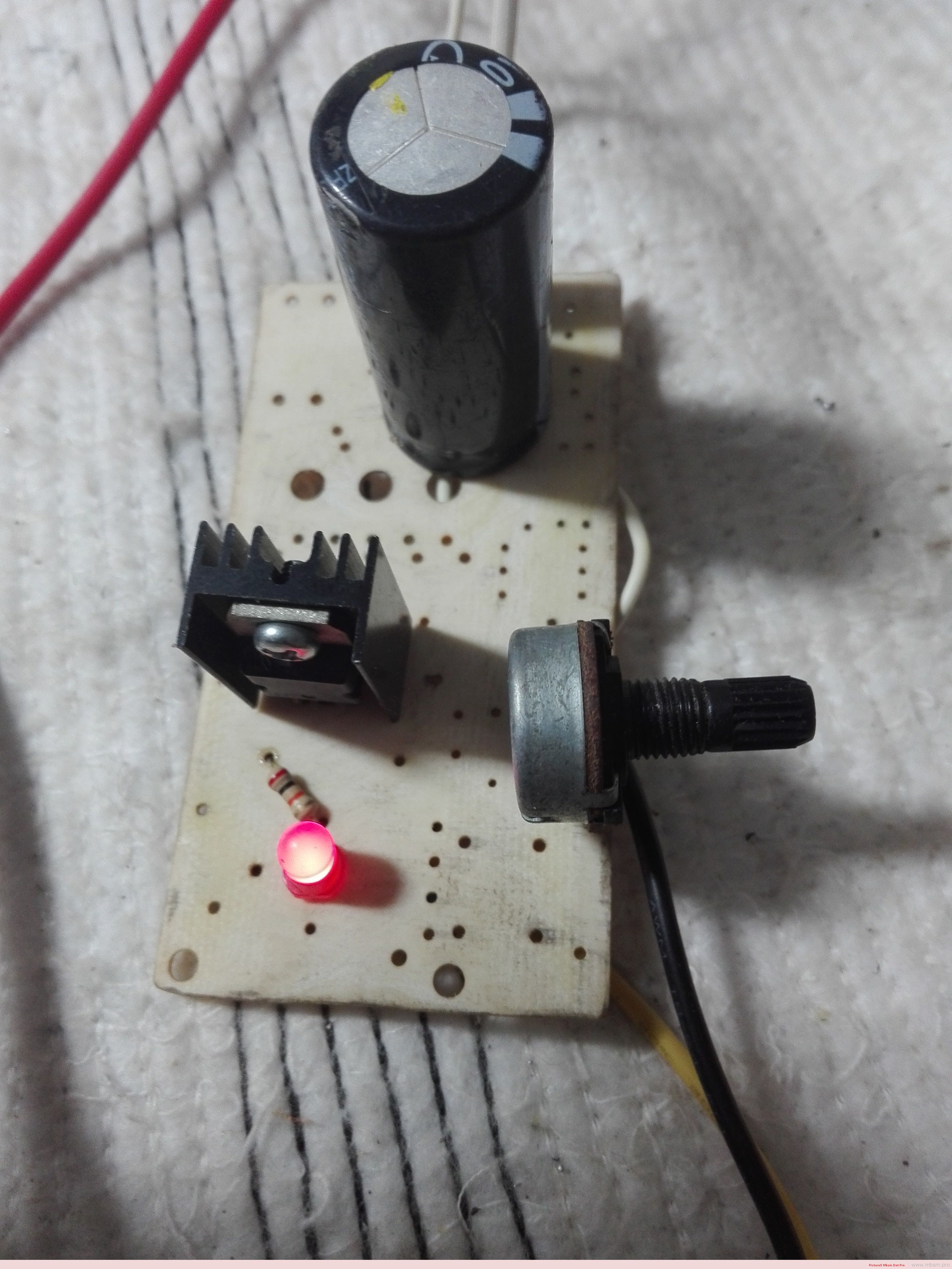
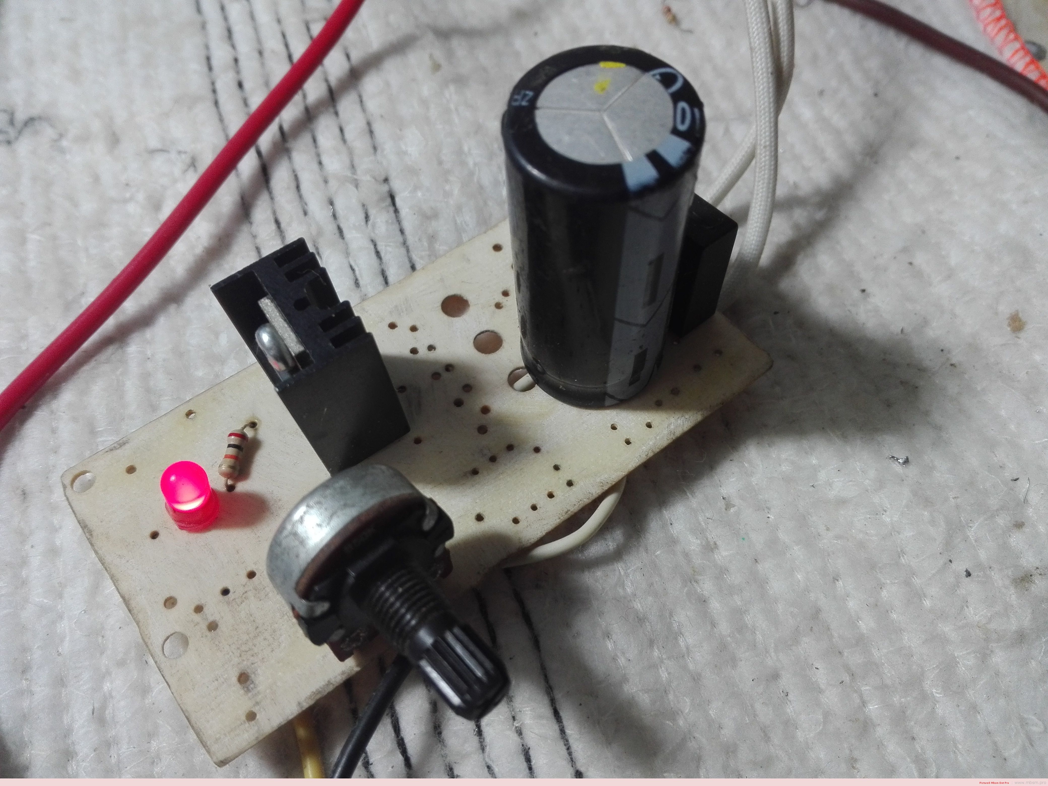
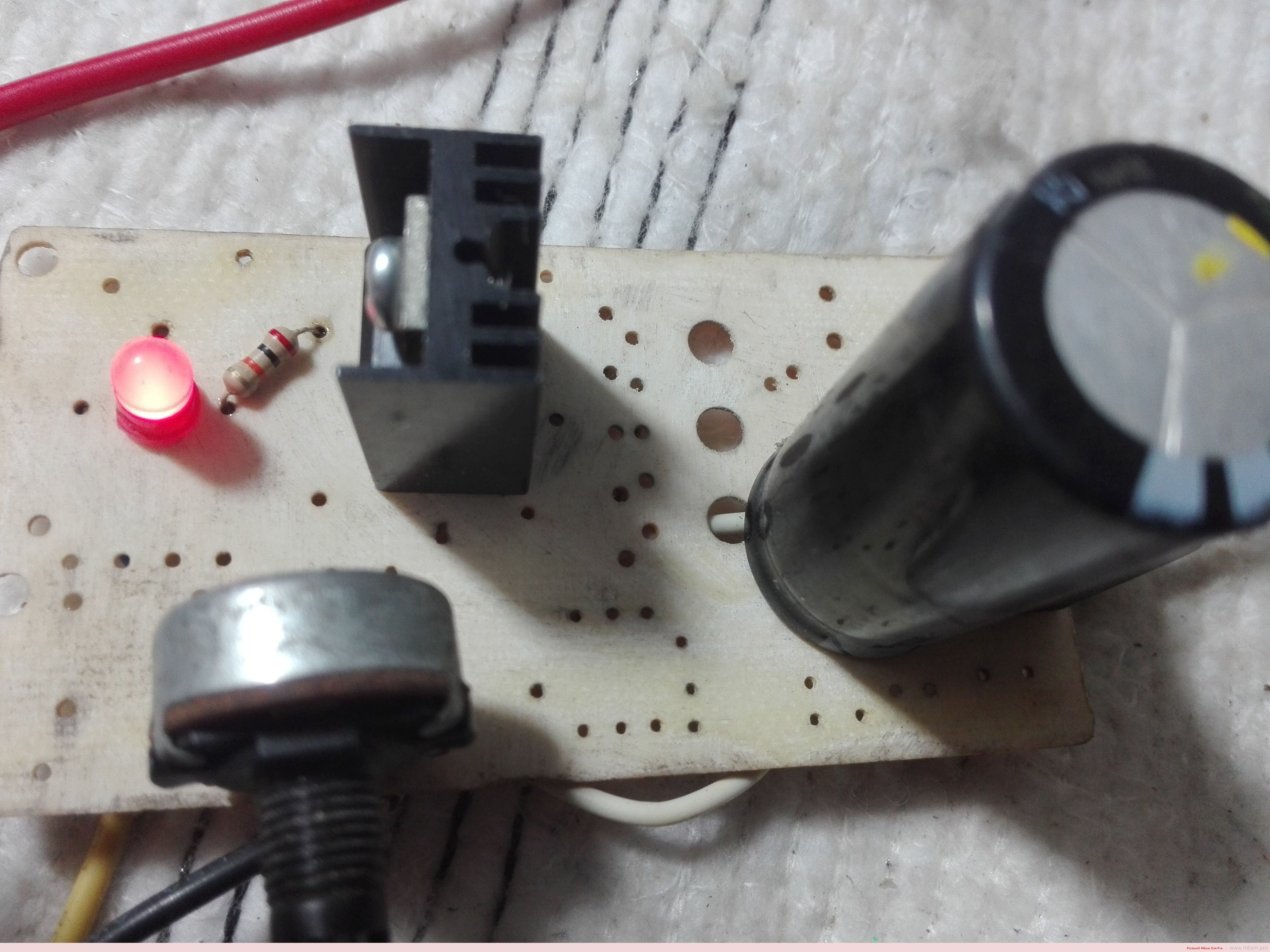
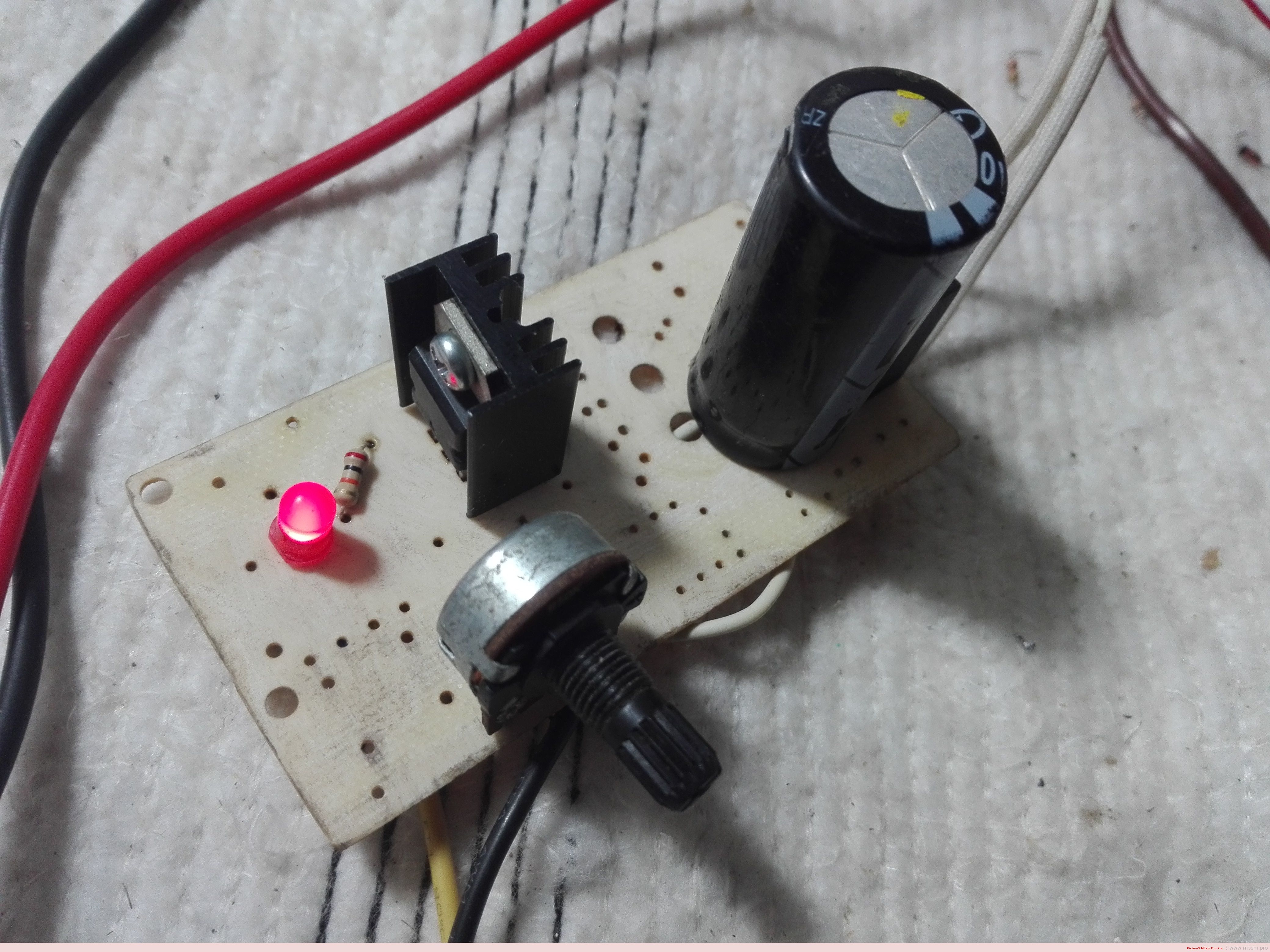
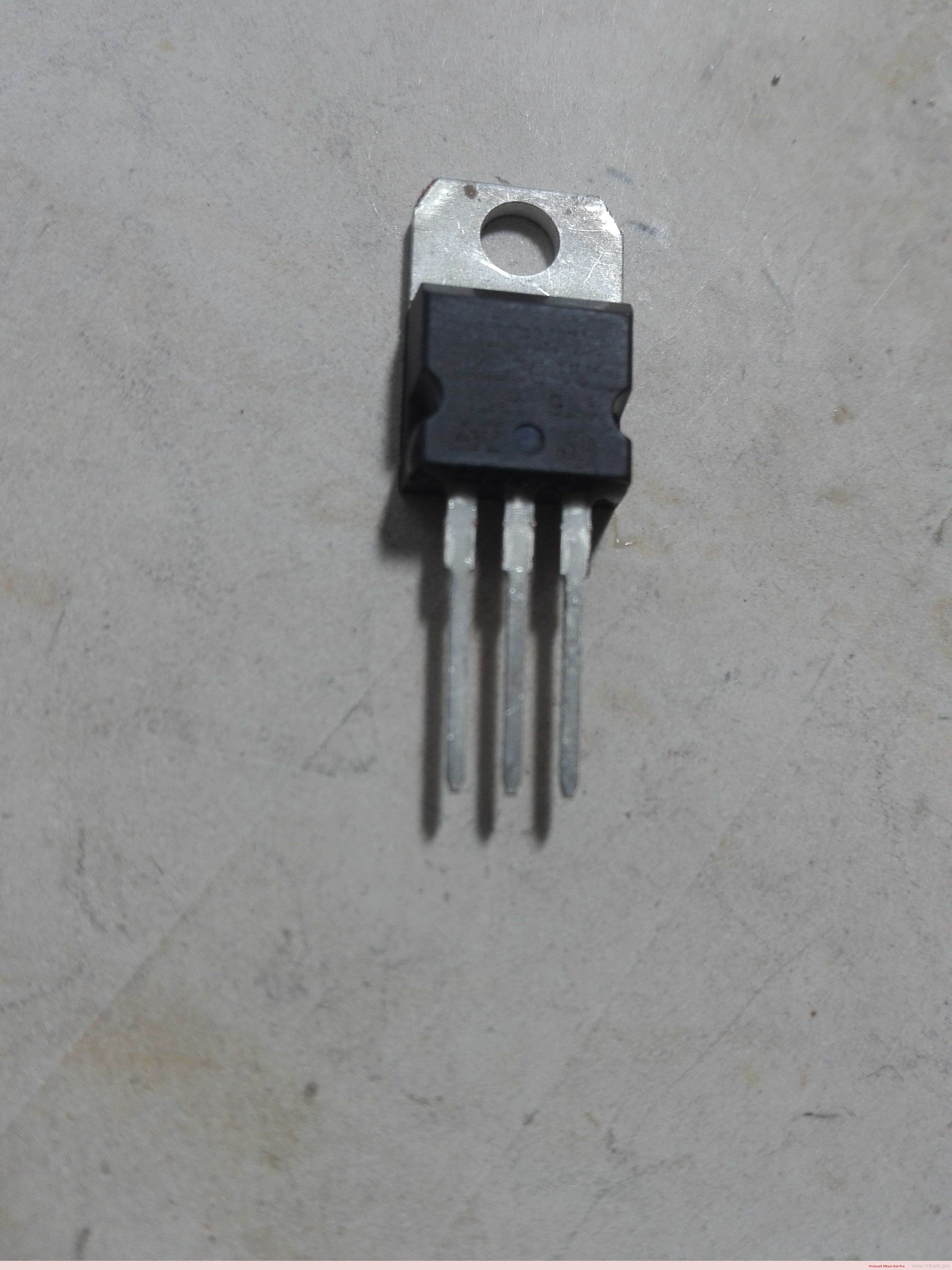
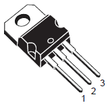
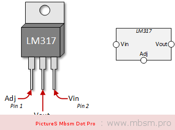
Mbsm.pro , LM317 ,Voltage Regulator Pin Outs, Simple test, voltage regulators ics , Voltage regulator

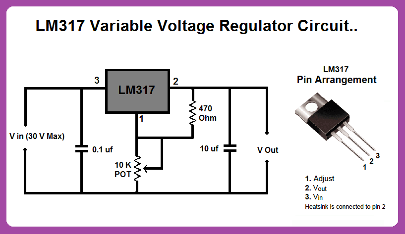
The LM317 is most commonly found in a TO220 package.  It only has three pins and we will be using all of them in this tutorial.

The LM317 Voltage Regulator for Current Control

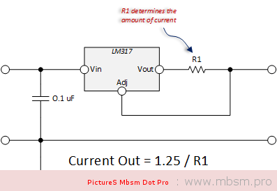
The use of an LM317 as a constant current source comes right from the data sheet.     The schematic below shows how to configure the LM317 as a current regulator.   It is the value of R1 that you will be concerned about and that value is determined by the type of LED you are using.


The math is really simple. The factor of 1.25 also comes from the data sheet.

Let’s walk through an example:

  1. Lets say you wanted to control to 300 mA.    You would determine that your optimum resistor is:
    R1 = 1.25 / 0.300 = 4.17 Ohms
  2. Next you’re going to poke around in your box of resistors to see what you’ve got.  You probably won’t find that 4.17 Ohm resistor, so you will want to try something close.   I had a 4.7 Ohm resistor.
  3. Now you’re going to want to apply the formula to see what that gets you.
    Current Out = 1.25 / 4.7 = 266 mA.
  4. Finally, we need to do a sanity check of the power rating of the resistor.   Here we will use I2 x R to get the power dissipated by the resistor.
    Power Dissipated by Resistor = 0.2662 x 4.7 = 0.332 Watts   (a half watt resistor will do the trick)


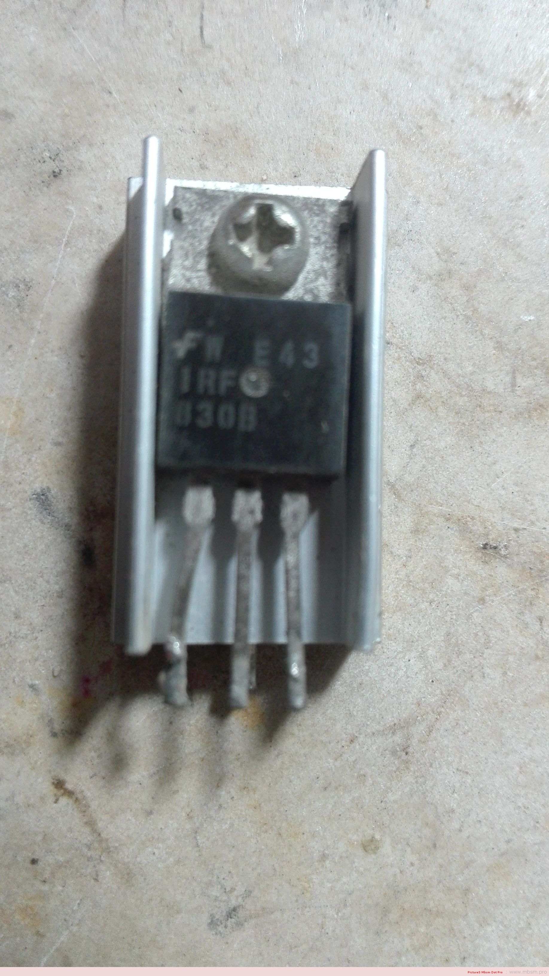
Mbsm.pro, IRF830 MOSFE , in power seplay , old Fortec star 3000

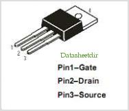
IRF830 pinout,Pin out

Type Designator: IRF830

Type of Transistor: MOSFET

Type of Control Channel: N -Channel

Maximum Power Dissipation (Pd): 100 W

Maximum Drain-Source Voltage |Vds|: 500 V

Maximum Gate-Source Voltage |Vgs|: 20 V

Maximum Gate-Threshold Voltage |Vgs(th)|: 4 V

Maximum Drain Current |Id|: 4.5 A

Maximum Junction Temperature (Tj): 150 °C

Drain-Source Capacitance (Cd): 800 pF

Maximum Drain-Source On-State Resistance (Rds): 1.5 Ohm

Package: TO220

Use the motor voltage and current specifications (either from the data sheet or from experimentation) to determine which transistors to choose. Selecting transistors with greater capacity will provide a margin of safety in your design.

For the purposes of this tutorial, I am using motors specified at 6V where they draw approximately 130mA. I will choose transistors I happen to have in my parts box. If I didn’t have anything on hand that would work, I would buy something that could handle 2X the voltage and current.

Picture

The IRF830 is an E-Mode N-channel MOSFET rated at 500V with an continuous current rating of 4.5A and a pulsed current rating of 18A. This is more than adequate for these motors.

It also has an internal diode for back-EMF protection.

Picture

Picture

The IRF9530 is an E-Mode P-channel MOSFET rated at 100V with a continuous current rating of 7.5A and a pulsed current rating of 48A. It is also more than adequate for my needs.

It also has an internal diode of back-EMF protection.

The pin out of the IRF9530 if the same as that of the IRF830 – Gate = pin 1; Drain = pin 2; Source = pin 3 (when viewed from the front.)
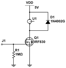

Picture

Motor connected from +V to transistor
Always use an N-channel MOSFET when the transistor is directly connected directly to either -V or GND. In this configuration, the transistor’s source pin sinks current from the motor directly back to the power supply. A HIGH on the Gate turns the transistor ON.

D1 is an added external diode to offer the transistor back-EMF protection. It is not required when using a transistor such as the IRF830 because it already has an internal diode for the same purpose. It is shown here simply to show how it should always be connected when using a transistor without an internal diode. It will be omitted from future circuits unless necessary.

R1 is a pull down resistor to ensure a LOW signal to the gate unless it is specifically driven HIGH.

Connections: Drain to motor; Source to GND; Gate to control device.

J1 (the MOSFET gate) is typically connected to a micro-controller pin. A HIGH signal turns the MOSFET ON energizing the motor; a LOW signal turns the MOSFET OFF stopping the motor – LOW = motor OFF; HIGH = motor ON.

The advantage of this circuit is its simplicity; the disadvantage of this circuit is that the motor can only turn in one direction making it suitable for controlling a fan or pump, but, not for a reversible robot.
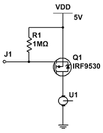

Picture

Motor connected from transistor to -V/GND
Always use a P-channel MOSFET when the transistor is directly connected to +V. In this configuration, the transistor’s drain pin channels current to the motor from where it will return to the power supply. A LOW on the Gate turns the transistor ON.

R1 is a pull up resistor to ensure a HIGH signal to the gate unless it is specifically driven LOW.

Connections: Drain to motor; Source to +V; Gate to control device.

J1 (the MOSFET gate) is typically connected to a micro-controller pin. A LOW signal turns the MOSFET ON energizing the motor; a HIGH turns the MOSFET OFF stopping the motor – LOW = motor ON; HIGH = motor OFF.

The advantage of this circuit is its simplicity; the disadvantage of this circuit is that the motor can only turn in one direction making it suitable for controlling a fan or pump, but, not for a reversible robot.

Depending upon desired motor response to specific logic levels, either of these circuits is well suited to function as described above.
Hisilicon Balong
Hisilicon Balong
Hisilicon Balong

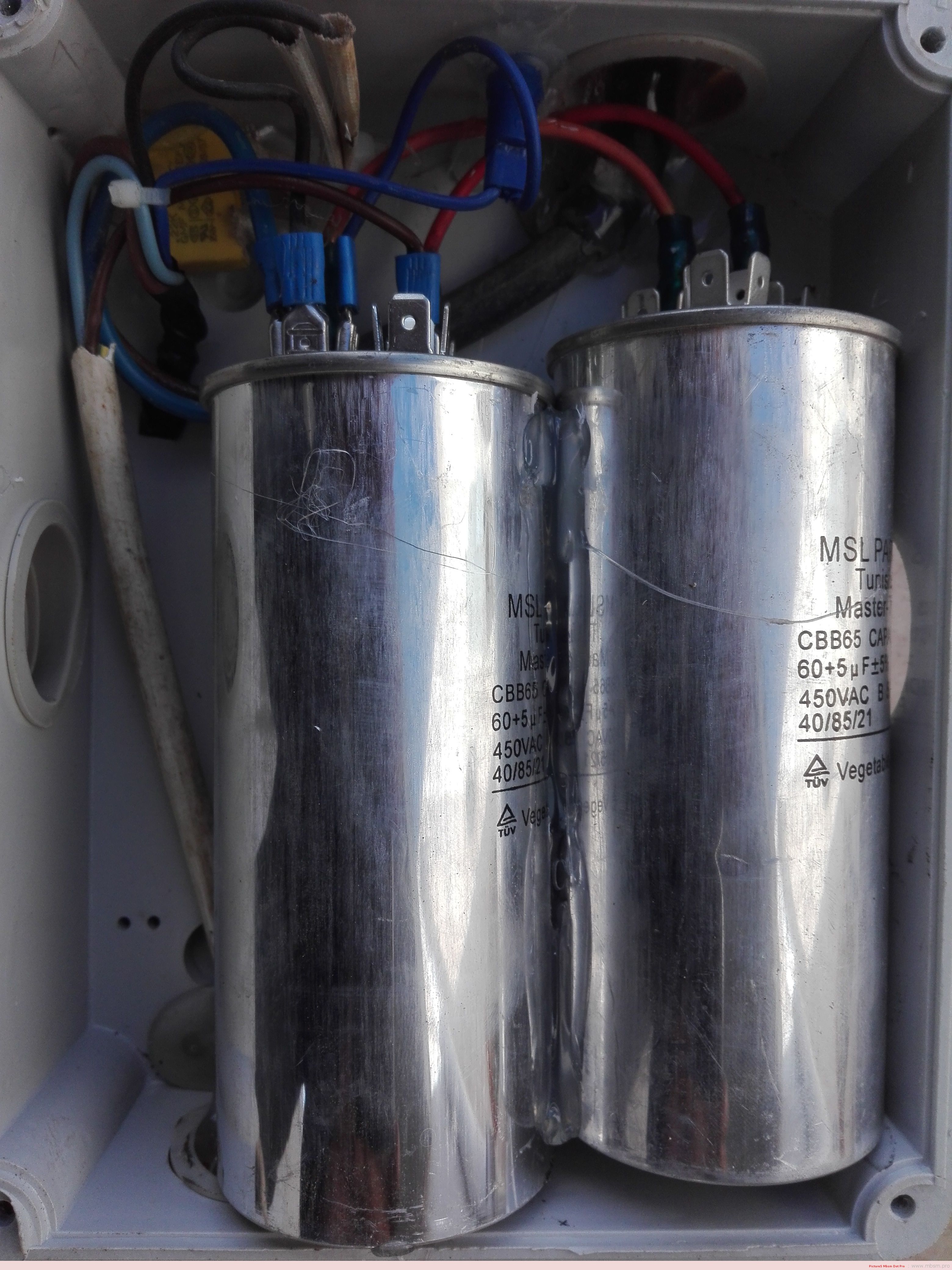
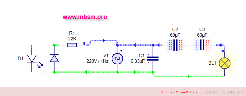
Mbsm.pro, Retardateur d’ampérage de démarrage , Exécution de 3000 W sur un ampérage max 10 a

Mbsm.pro, Retardateur d’ampérage de démarrage , Exécution de 3000 W sur un ampérage max 10 a

3000 w = 3000/220 v= 13.636 a

le but c’est démarrer une machine 3000 W sous un disjoncteur 10 A

10 A = 220 V * 10 A = 2200 W

3000 W – 2200 W = 800 w = 800 W /220 V  = 3.636 A


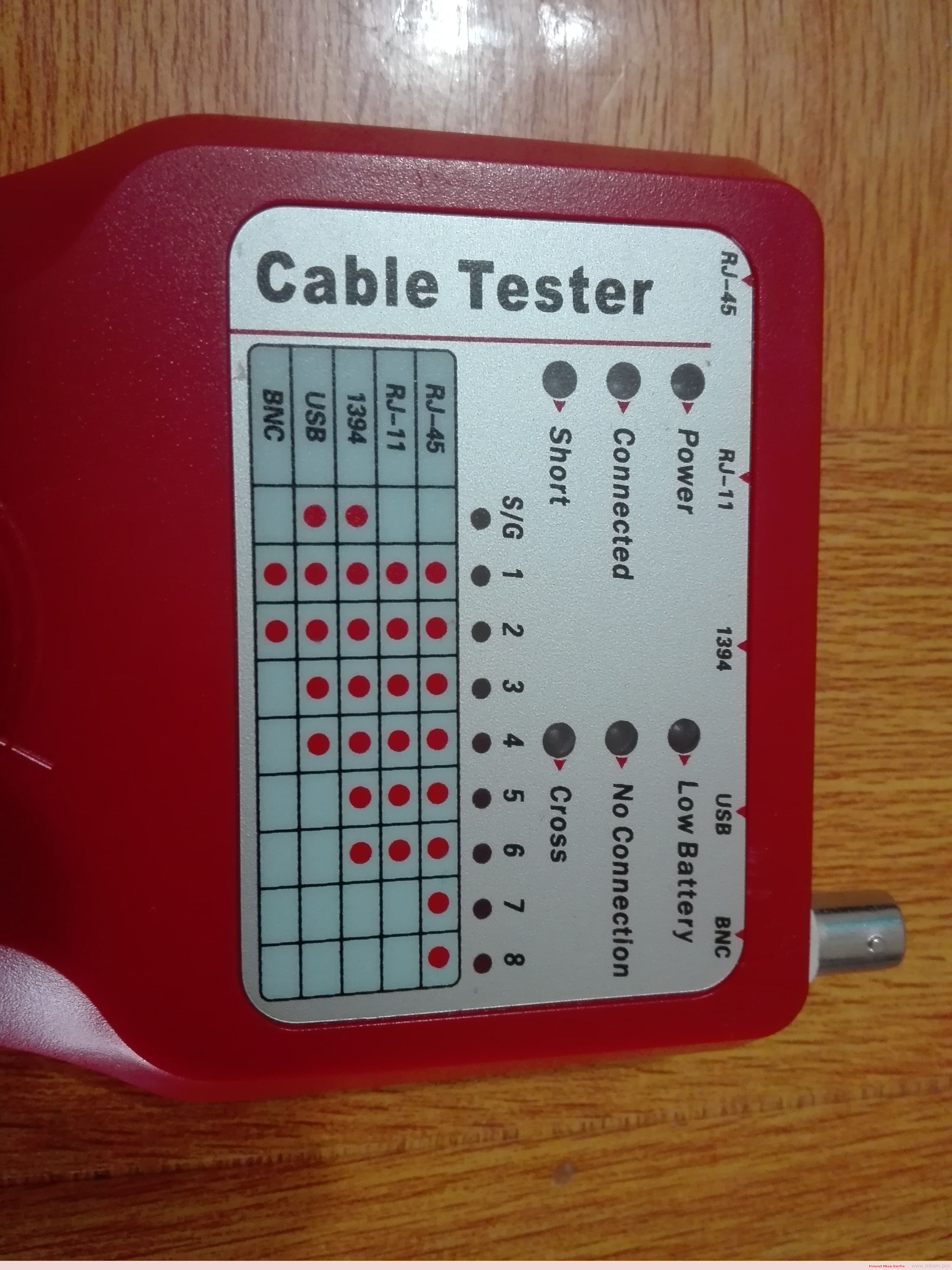
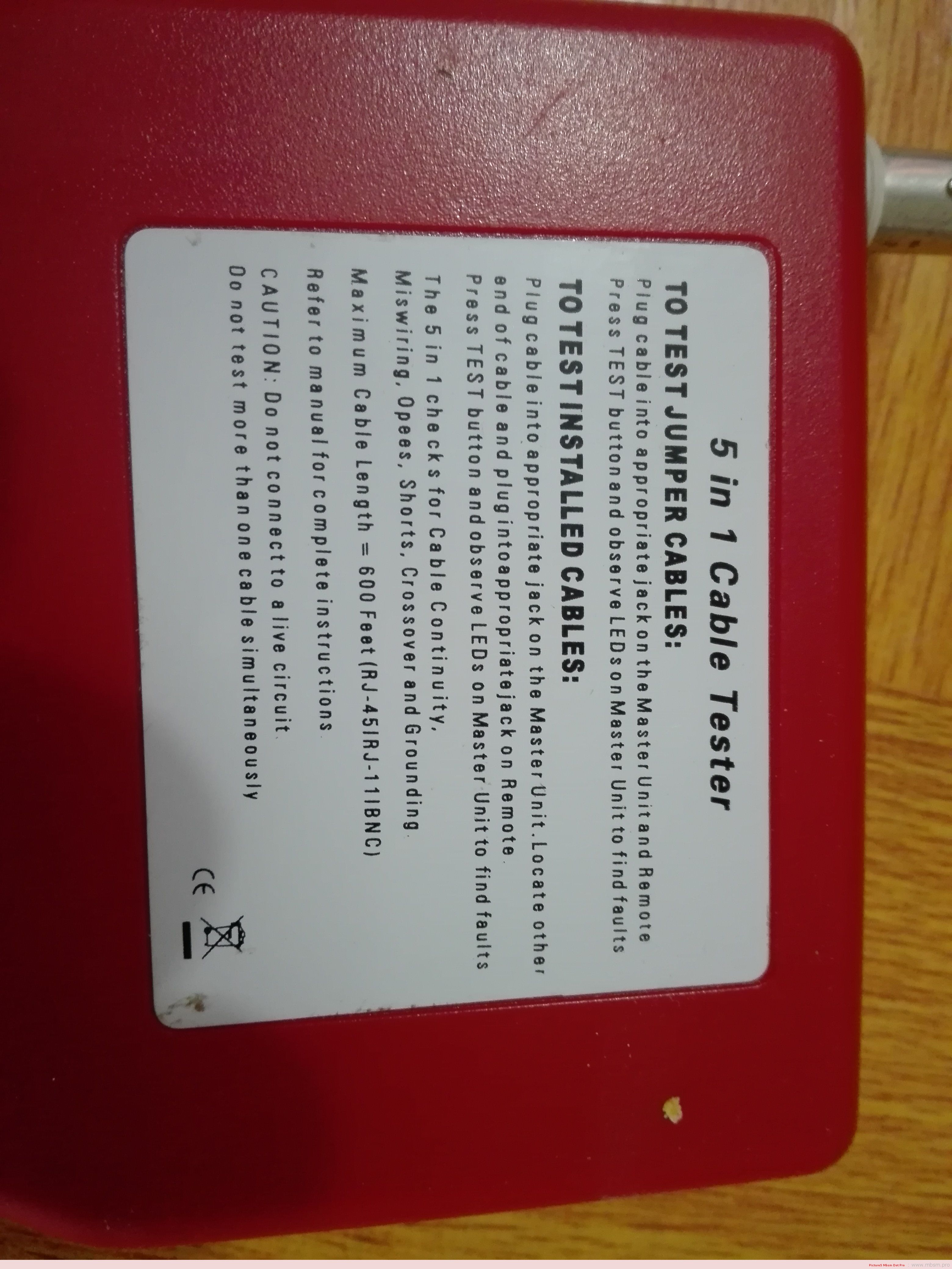
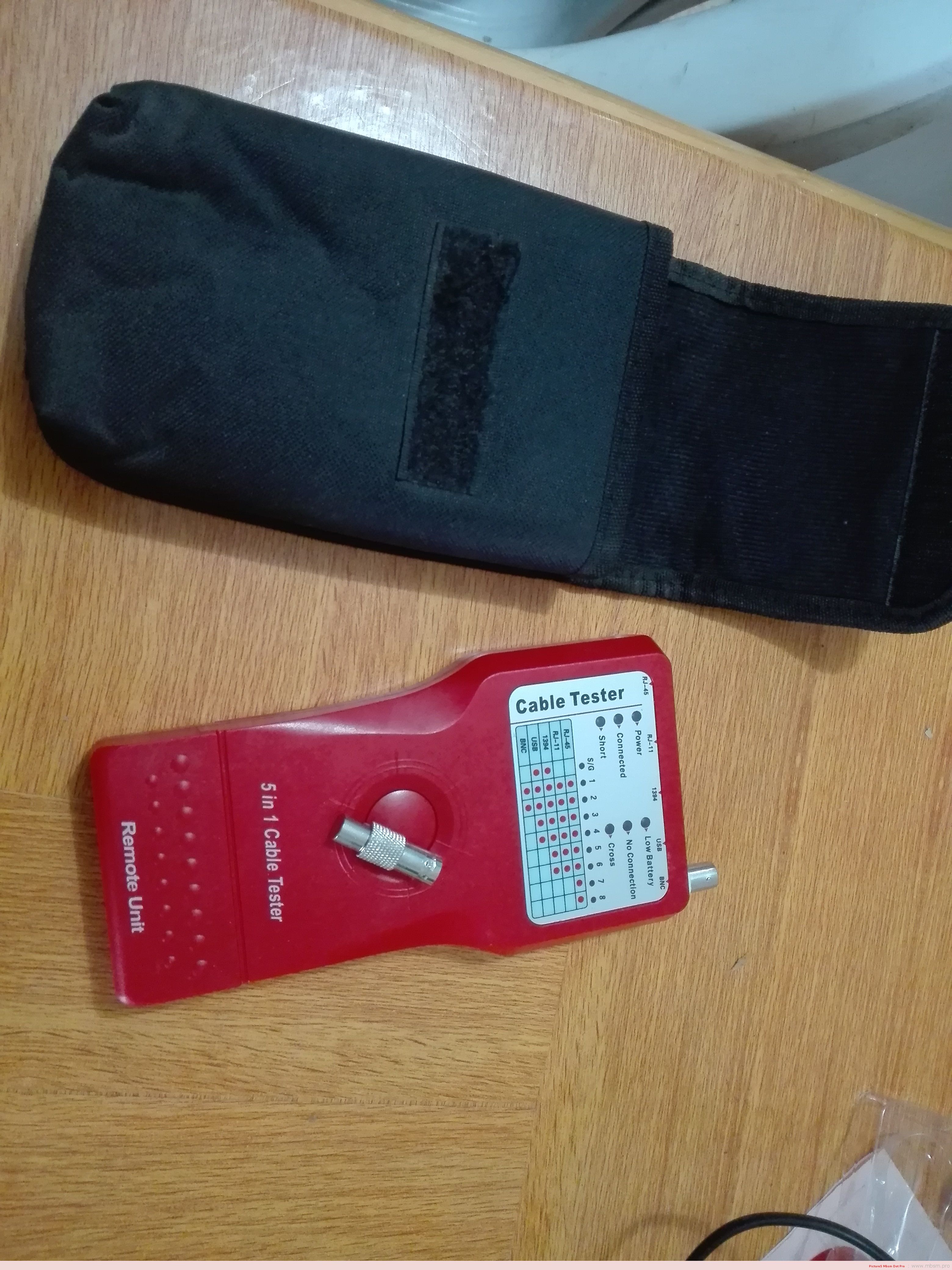
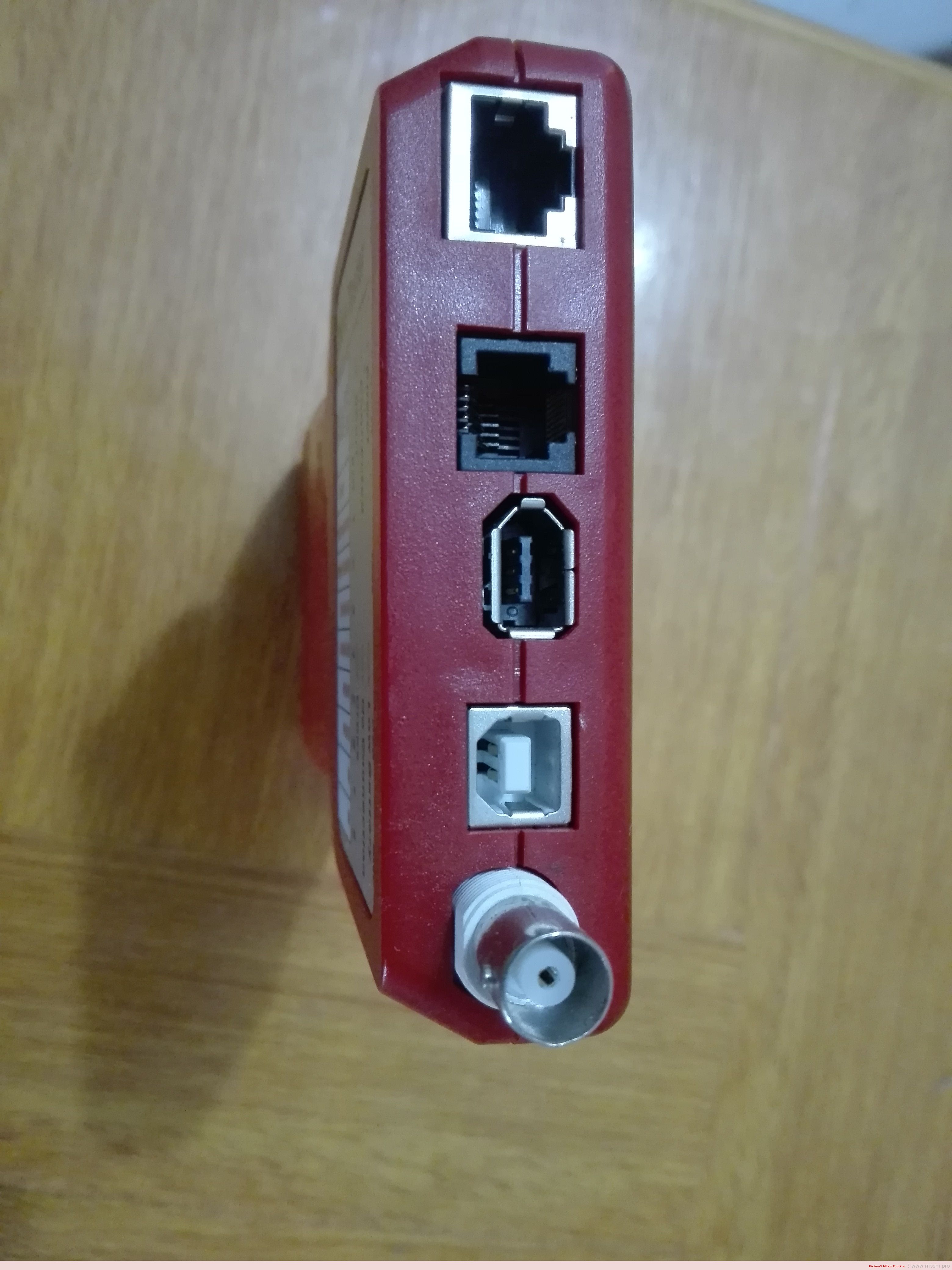
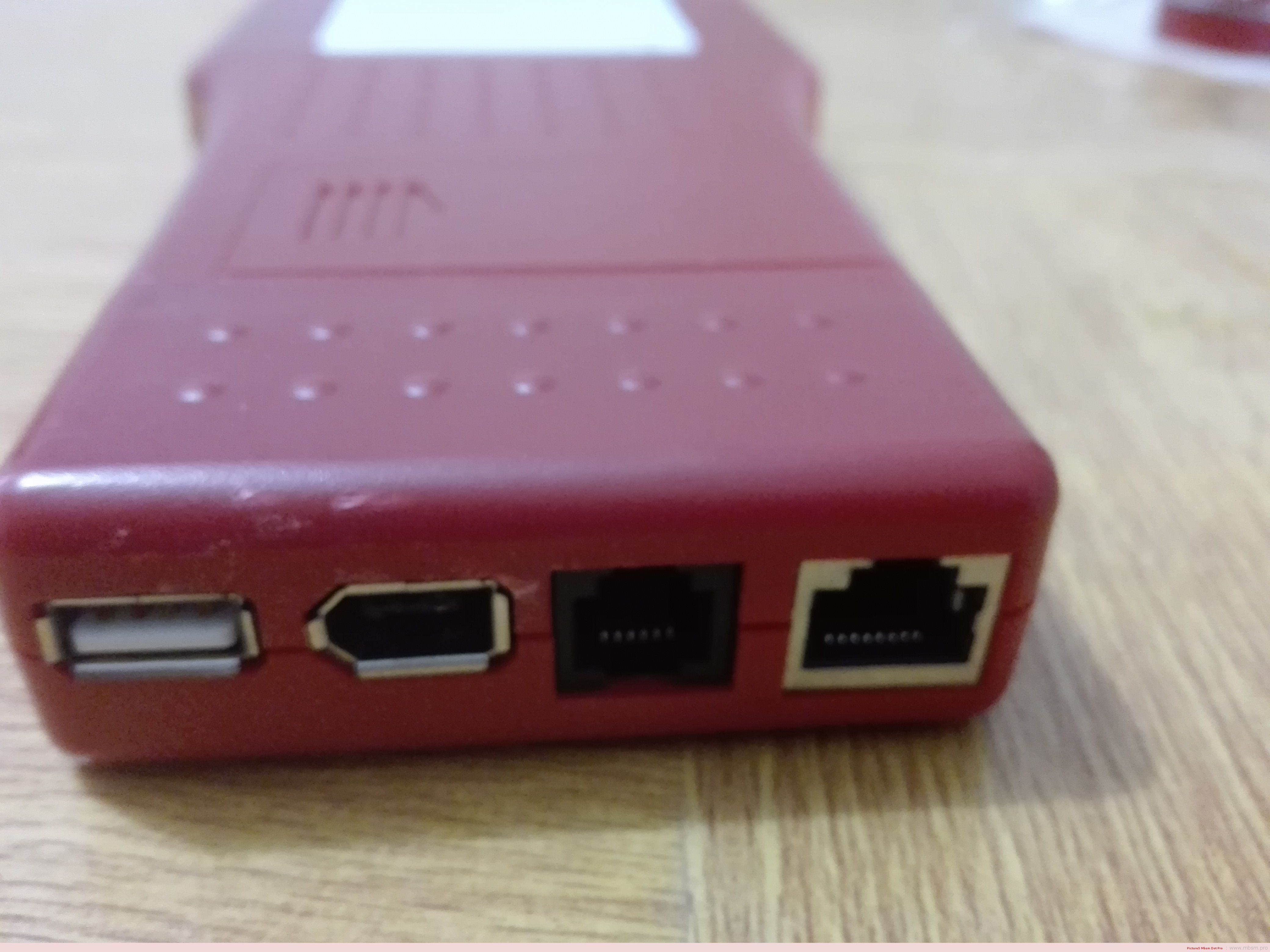
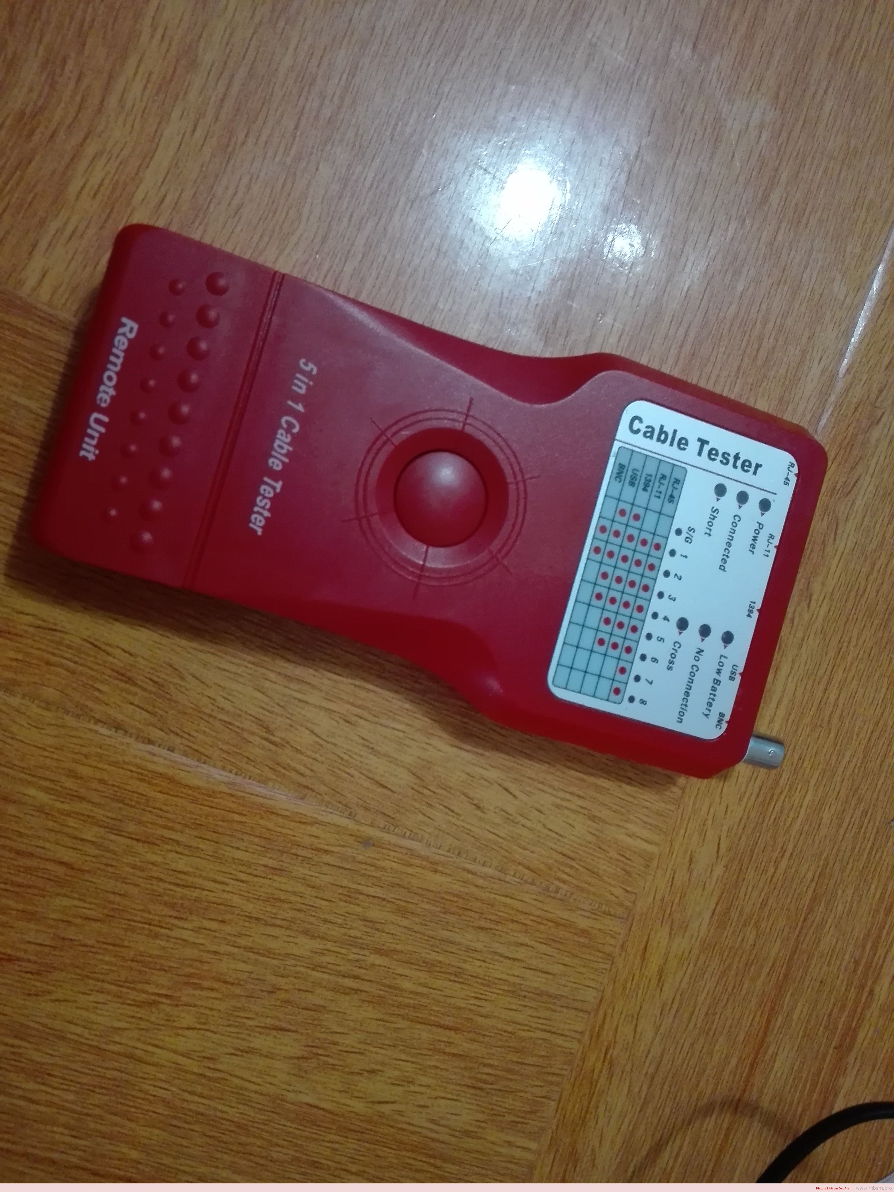
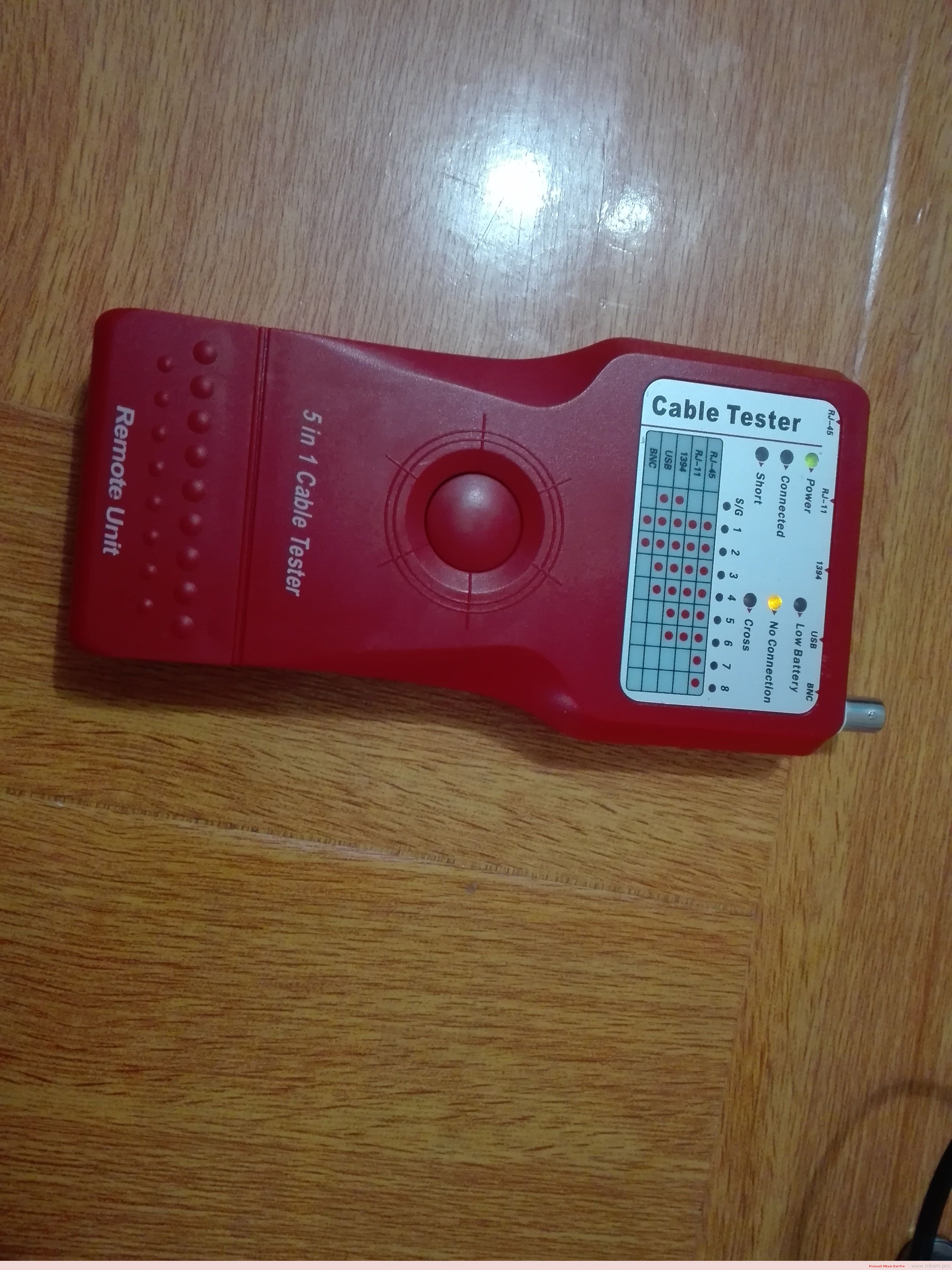
Mbsm.pro , Testeur de câble , camera (bnc connector) , USB, Rg45 , Rg11, Port 1394 , Produit tester, par mbsmgroup

Mbsm.pro , Testeur de câble , camera (bnc connecter) , USB, Rg45 , Rg11, Port 1394 , Produit tester, par mbsmgroup


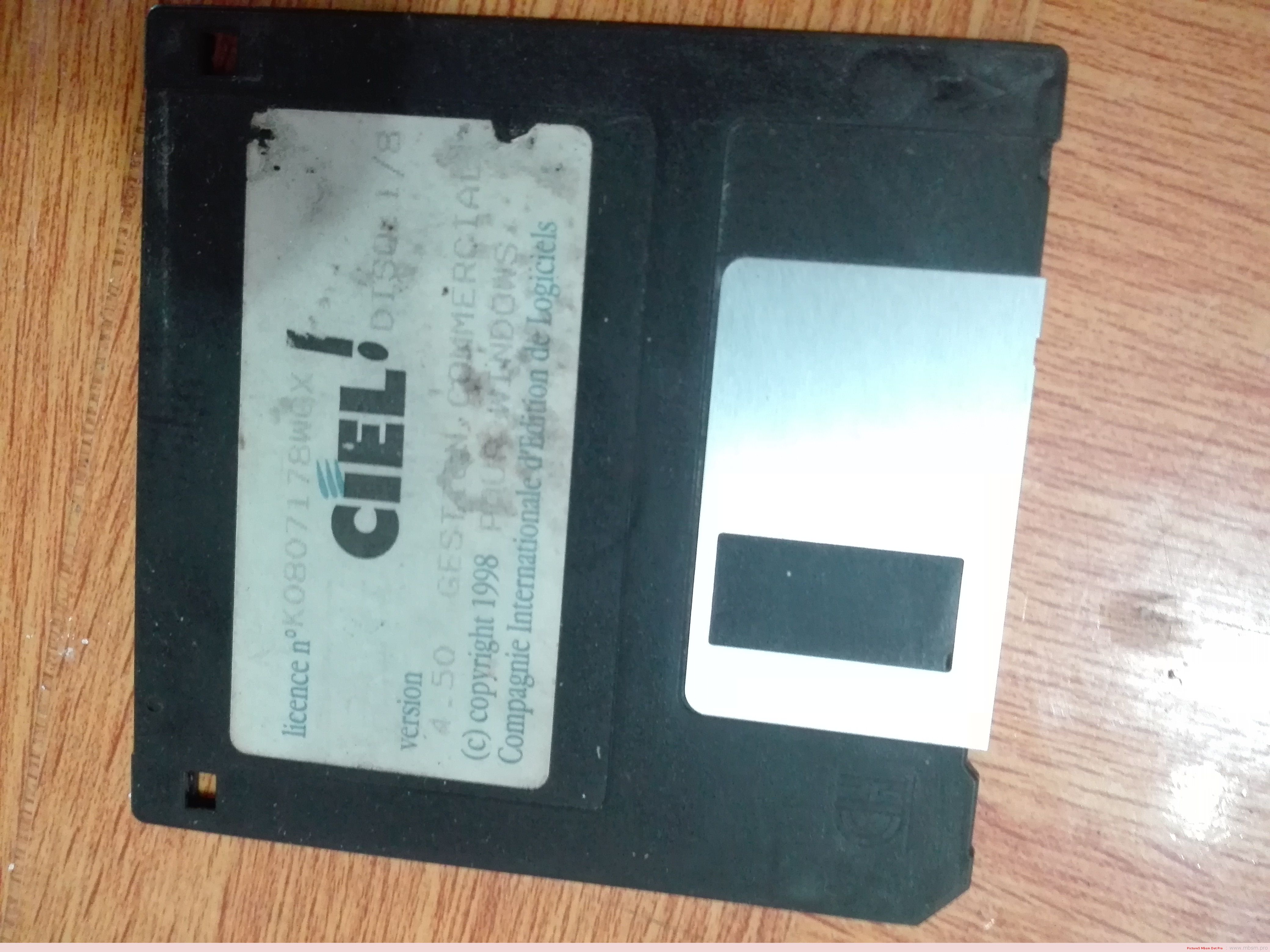
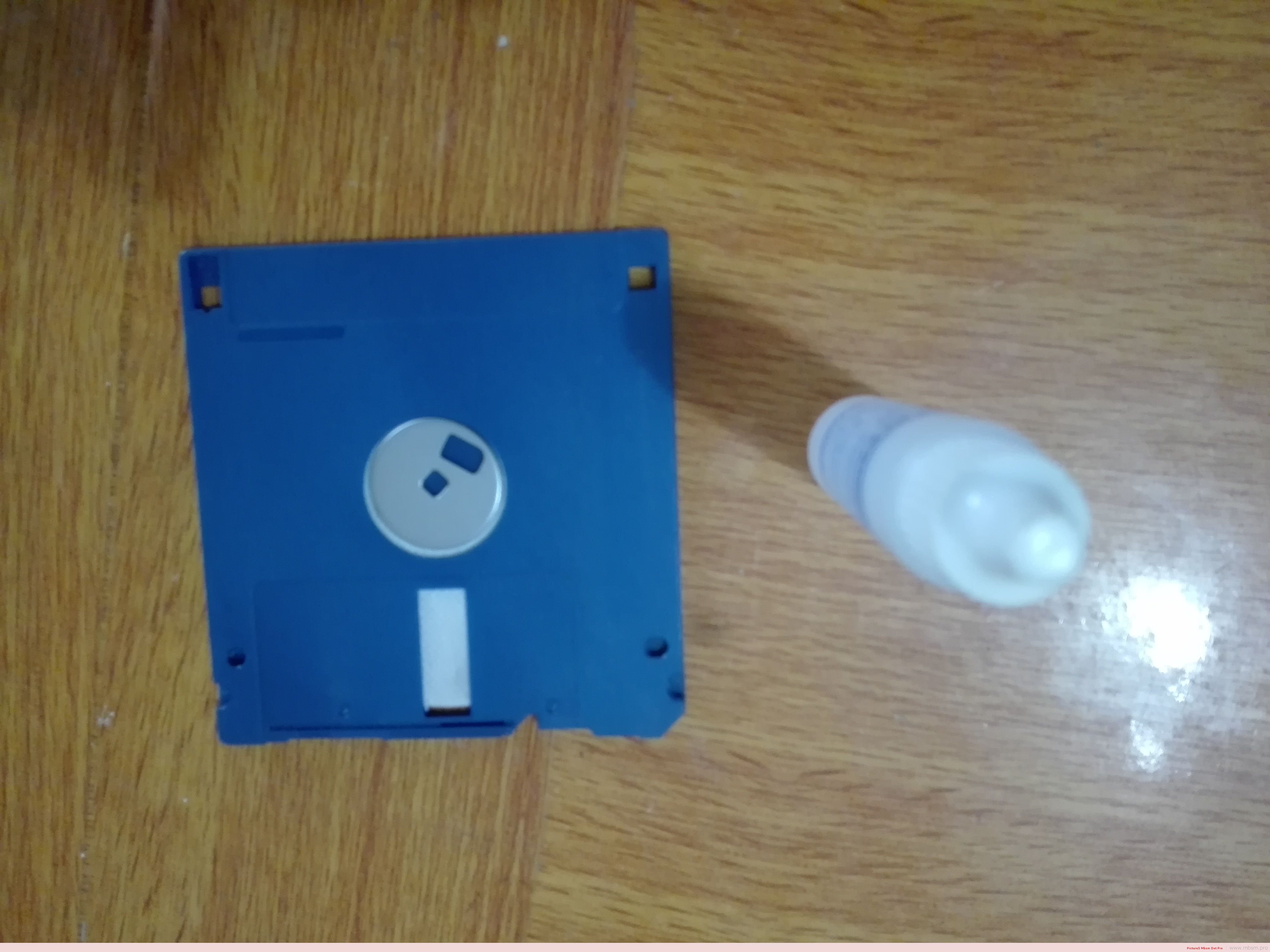
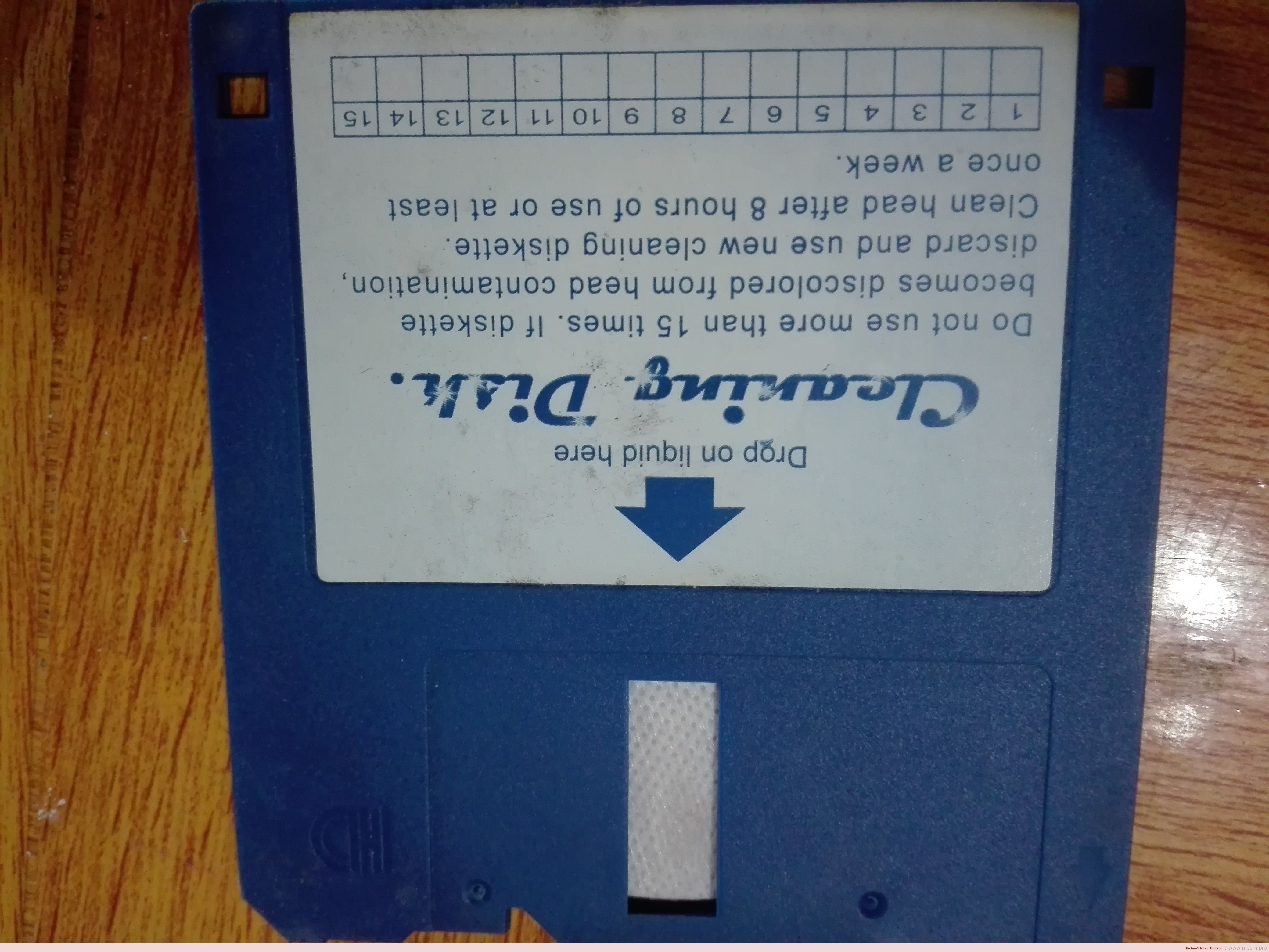
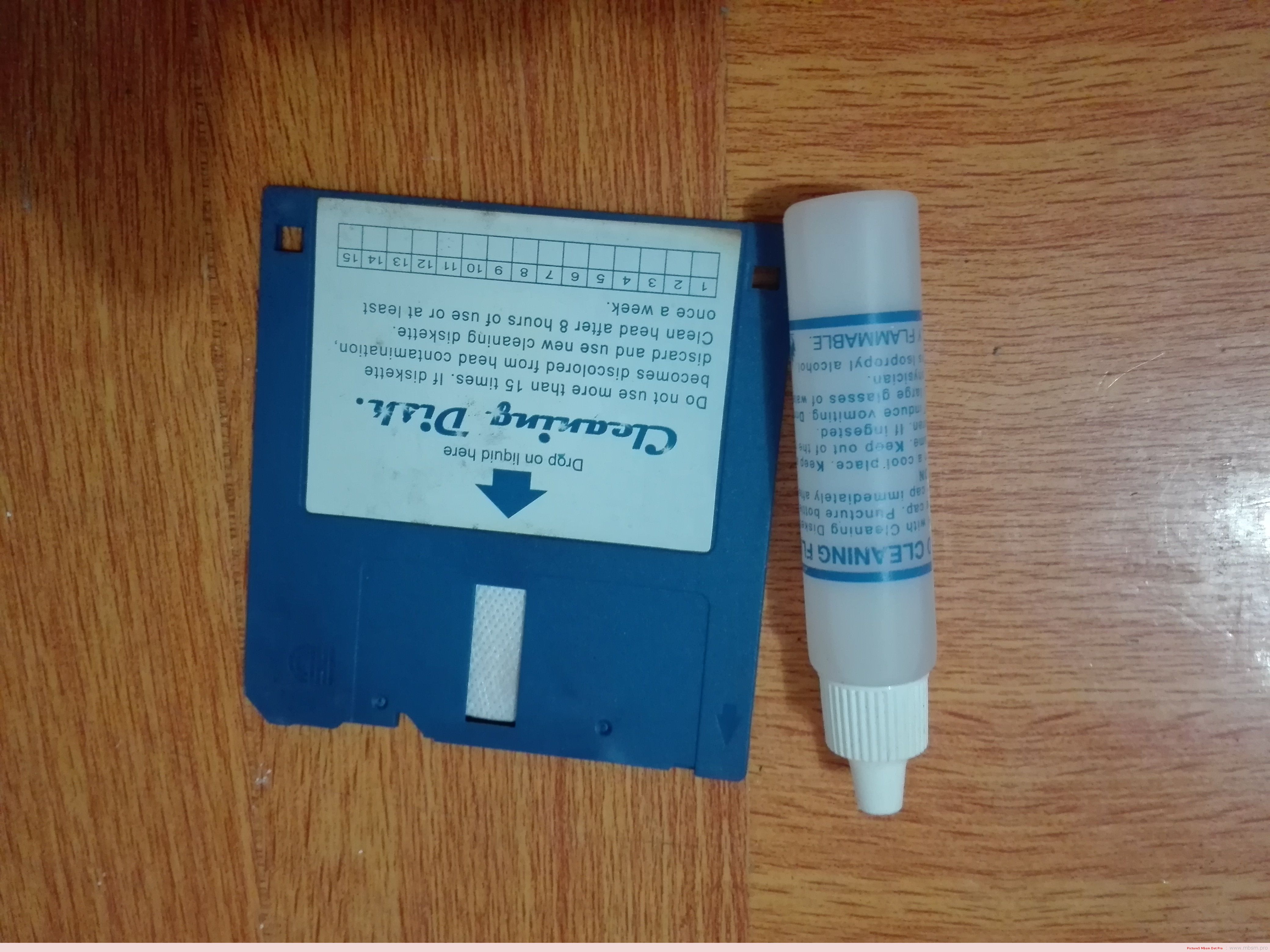
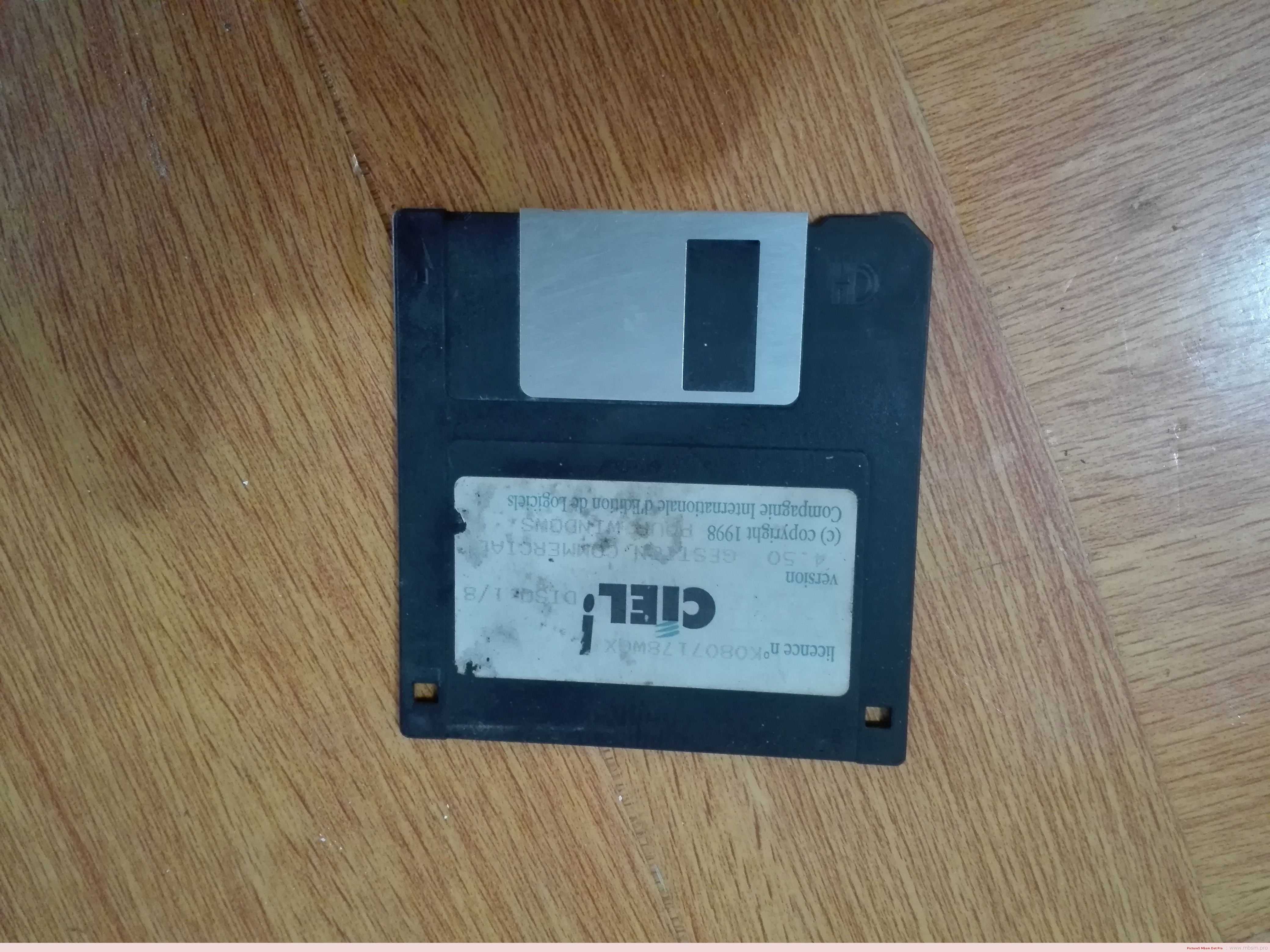
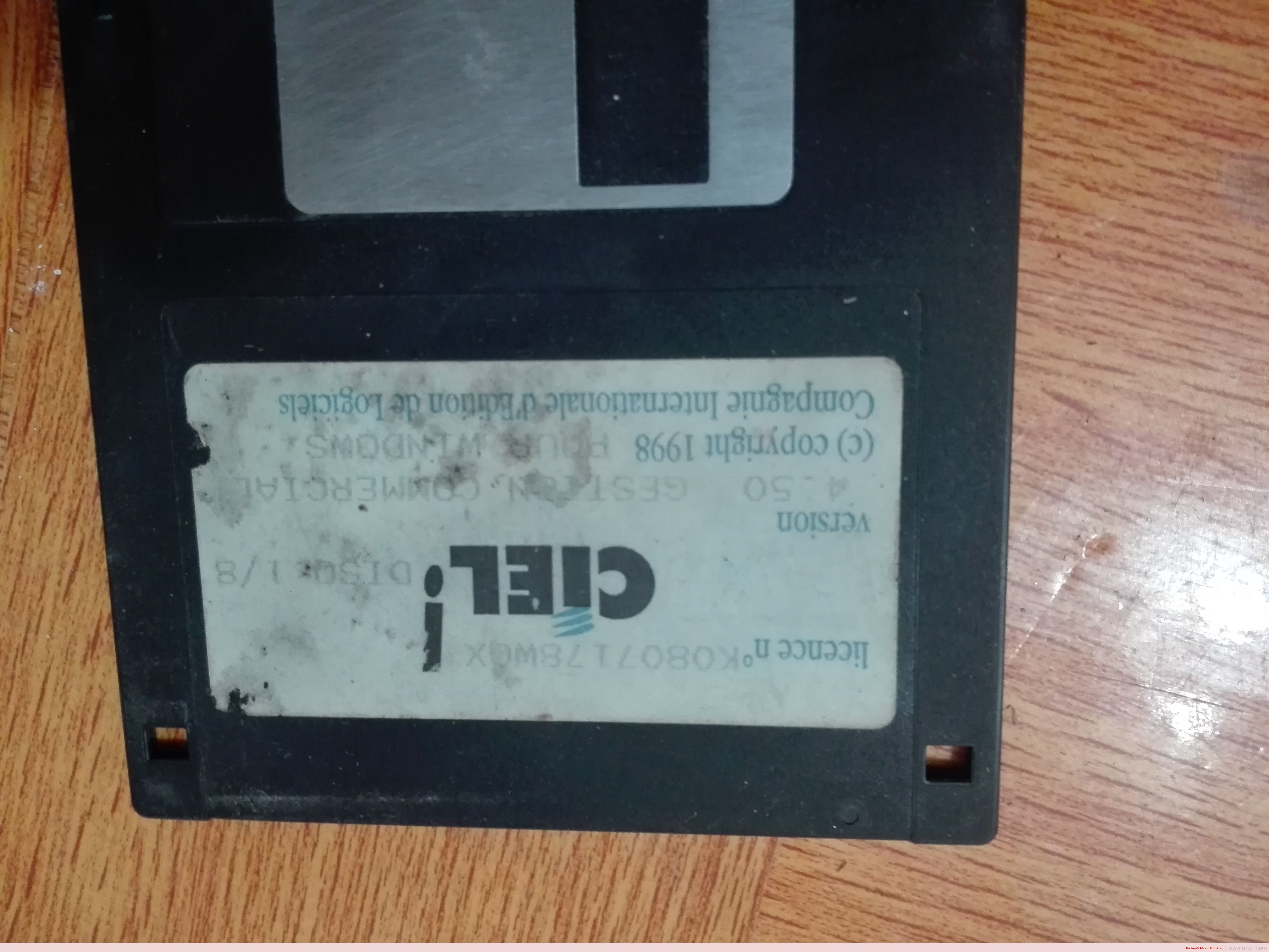
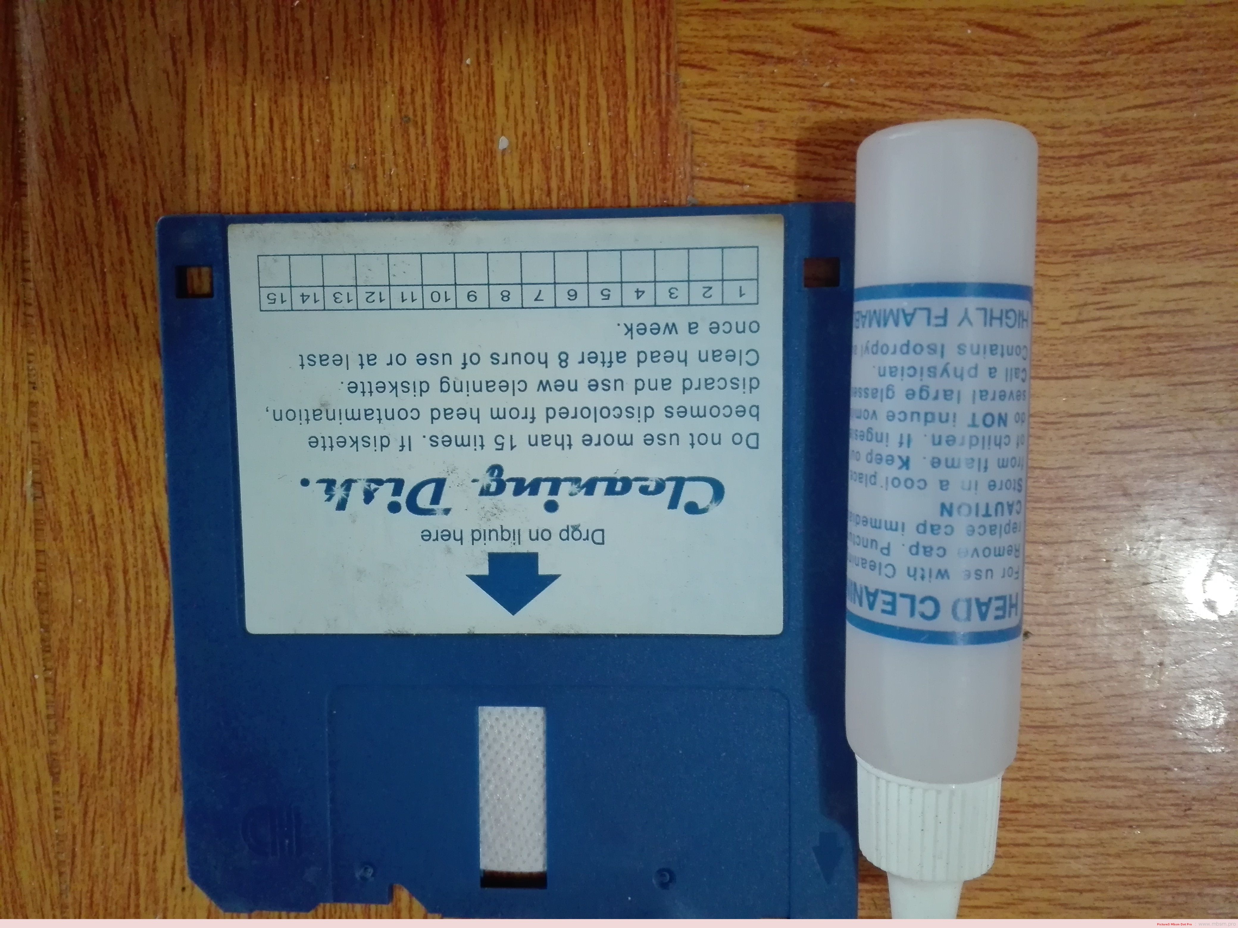
Mbsm.pro, 1998 , la première foie, je touche, une disquette pc ,et j’installe un logiciel

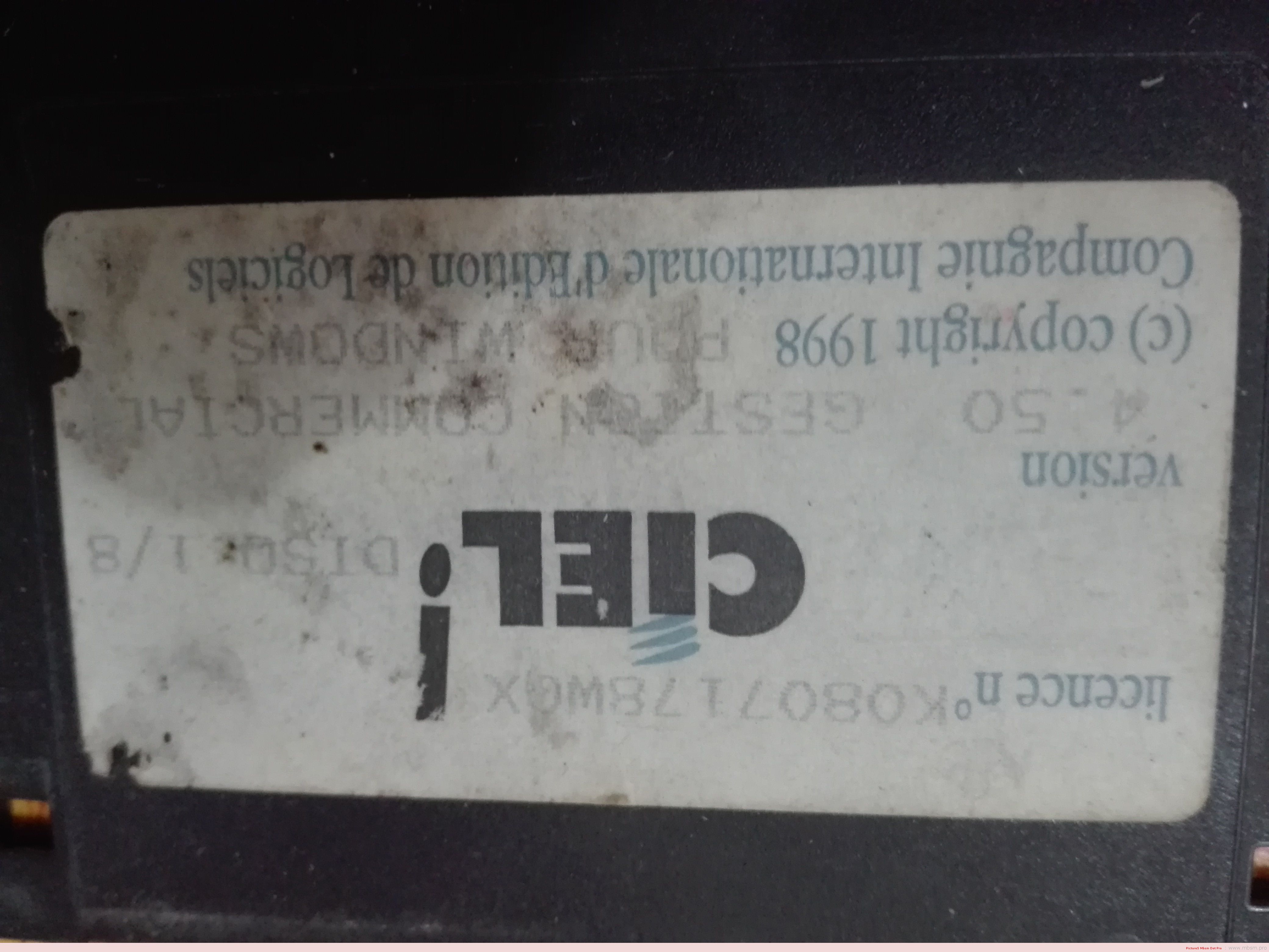
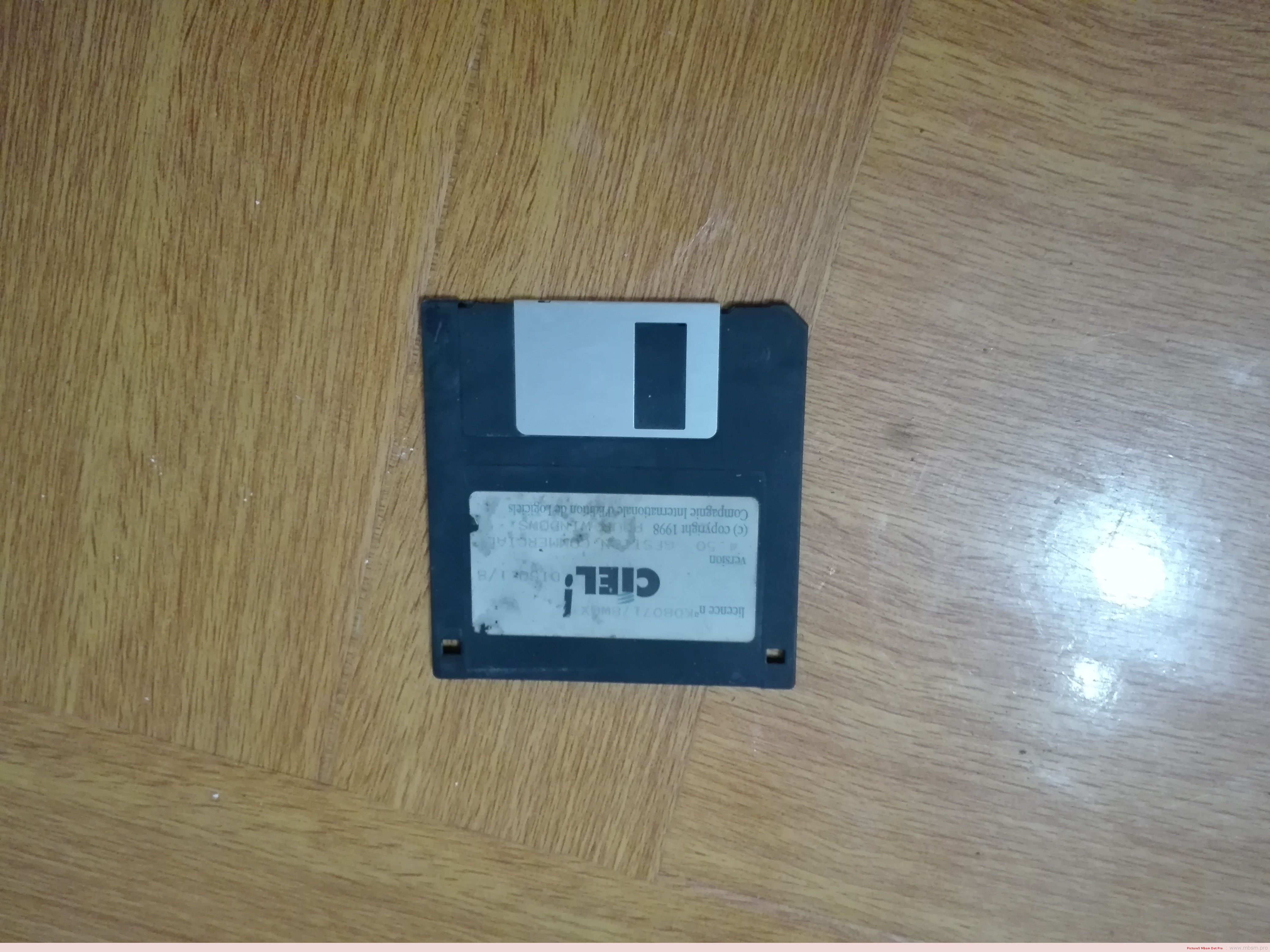
Mbsm.pro, 1998 , la première foie, je touche, une disquette pc ,et j’installe un logiciel


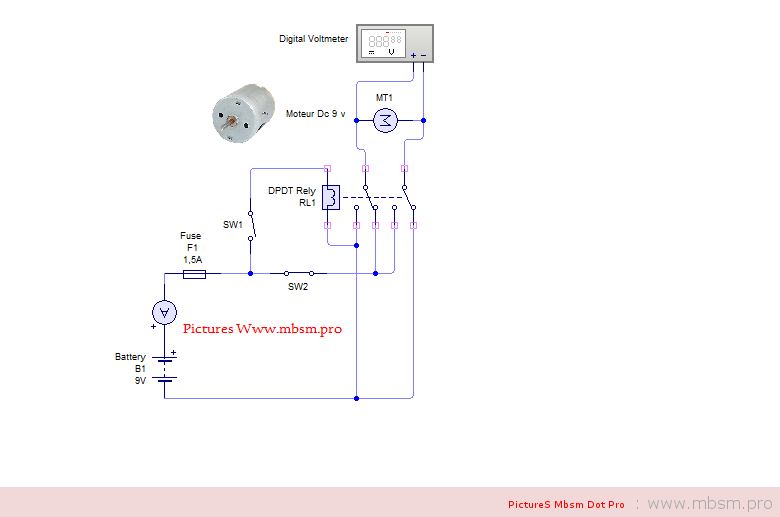
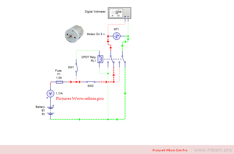
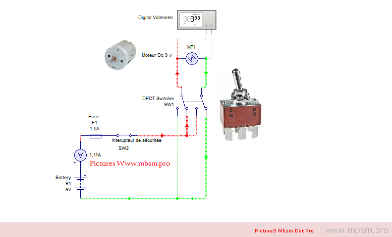
Mbsm.pro ,Inverser la rotation, d’un moteur 9v Dc, avec DPDT Rely

Mbsm.pro ,Inverser la rotation, d’un moteur 9v Dc, avec DPDT Rely

Mbsm.pro ,Inverser la rotation, d’un moteur 9v Dc, avec DPDT Rely


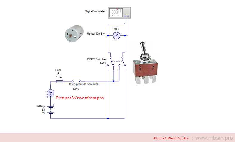
Mbsm.pro ,Inverser la rotation, d’un moteur 9v Dc, avec DPDT Switch

Mbsm.pro ,Inverser la rotation, d’un moteur 9v Dc, avec DPDT Switch

Mbsm.pro ,Inverser la rotation, d’un moteur 9v Dc, avec DPDT Switch


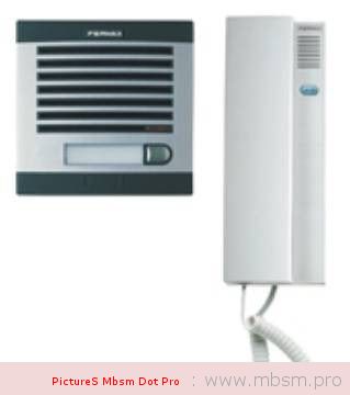
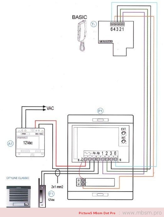
Mbsm.pro, Interphone FERMAX ,kit 6201, Schéma et manuel

Installation manuelle Kit Fermax 6201

Dans ce manuel, nous allons expliquer comment monter un kit d’entrée de porte pour une référence de logement Fermax 6201. Voici les éléments qui composent ce kit, supports systèmes et les éventuels problèmes que vous pouvez trouver avec leurs solutions. Commençons.

6201 kit Fermax est une ligne de kit 1 entryphone, ou ce qui est la même chose, pour 1 maison. Il est composé de:

  • Rue de la ville classique bord 4 + N avec 1 bouton d’appel, réf. 8 300
  • ref boîte murale. 8948
  • zone de surface (en option) réf. 8951
  • Téléphone de base Citymax ref. 80447
  • Alimentador 12Vac/1,5A-DIN4 ref. 4800

Panel.

Street Sign Ville classique est une carte conçue avec un profil courbe convexe, en aluminium anodisé haute résistance aux changements météorologiques et climatiques. boutons d’appel sont des boutons métalliques, qui peuvent être double ou simple. En appuyant sur le bouton d’appel, il est confirmé par un signal acoustique provenant de l’amplificateur. La poussée comprend une fente de carte à insérer une étiquette d’identification. En appuyant sur la lumière à l’avant de l’amplificateur, une lumière douce permet de voir les emplacements de carte. L’amplificateur comprend un éclairage avant du bouton de microphone électrique, les réglages de volume dans les deux directions pour un niveau acoustique libres couplages acoustiques et confirmation d’appel. Une fois que l’unité est installée la plaque,

Téléphone Citymax Basic.

Citymax téléphone de base est en plastique ABS avec un type de finition « poli miroir » pour faciliter le nettoyage. Il a plusieurs points d’ancrage pour le montage mural, ainsi que le cordon enroulé avec des connecteurs de type fiche téléphonique. Son fonctionnement est essentiel. Après avoir reçu l’appel, vous pouvez avoir une conversation avec le panneau. Pour ouvrir la porte, il suffit d’appuyer sur le bouton avec la touche.

MONTAGE

Pour connecter des fils, Fermax fait suite à une série de critères attribuant un numéro aux différentes fonctions, qui sont:

  • 1: OUVERTURE
  • 2: MICROPHONE
  • 3: fil conducteur
  • 6: SPEAKER
  • 4: BUZZER

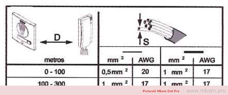
Pour le raccordement des câbles doit prendre en compte la section de celle-ci, qui se trouve dans le tableau suivant:

En ce qui concerne le câble d’alimentation, il peut utiliser un câble UTP reliant plusieurs fils ensemble pour le rendre plus résistant, ou d’un tuyau deux fils de phase et neutre.

PROBLÈMES POSSIBLES.

Dans cette installation, nous pouvons trouver un certain nombre de problèmes différents. Ici vous avez le plus en commun avec leurs solutions.

– Non suenta la cloche, mais il y a communication entre la plaque et l’interphone.

  • Le fil peut vous appeler sont lâches ou cassés.
  • Le téléphone peut être hors du crochet, de sorte qu’il ne sonnera pas.

– Sons appel, mais il n’y a pas de communication avec le conseil d’administration.

  • Les fils des haut-parleurs et microphone peuvent être connectés de manière incorrecte ou cassés.
  • rue plaque de volume audio pourrait être très faible.


Mbsm.pro , extension Unshorten.It sur Google Chrome et Firefox pour vérifier les liens et trouver rapidement et facilement leur adresse d’origine

Vous pouvez utiliser l’extension Unshorten.It sur Google Chrome et Firefox pour vérifier les liens et trouver rapidement et facilement leur adresse d’origine au lieu de copier le lien et d’ouvrir le site vous-même et de le coller là.
C’est bien si votre temps est précieux et que vous voulez sauver quelques secondes de votre vie, car tout ce que vous avez à faire est de cliquer avec le bouton droit de la souris sur n’importe quel raccourci, puis sur Unshorten ce lien pour obtenir l’information que vous voulez